
System Design
Streamline and Enhance Your System Design with D-Tools
From marked up floor plans to precise engineering drawings, D-Tools offers the ultimate platforms to boost your system designs.
 System Integrator
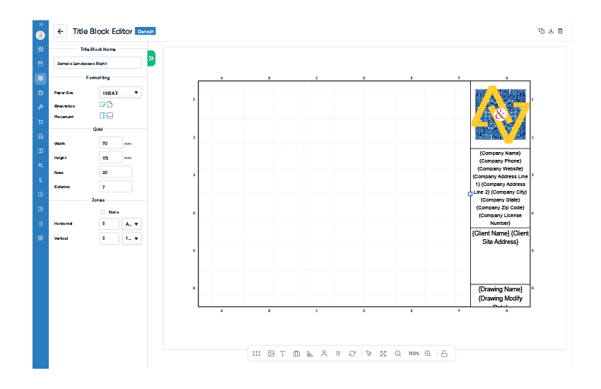
Detailed Engineering Drawings & Project Documentation
Create detailed, engineered drawings—including single-line system layouts, plan views, rack elevations, and schematics—to ensure clear communication with both internal teams and external stakeholders through native integration with Visio and AutoCAD, making it easy to produce professional drawings that improve collaboration and project accuracy.


.svg) D-Tools Cloud
D-Tools Cloud
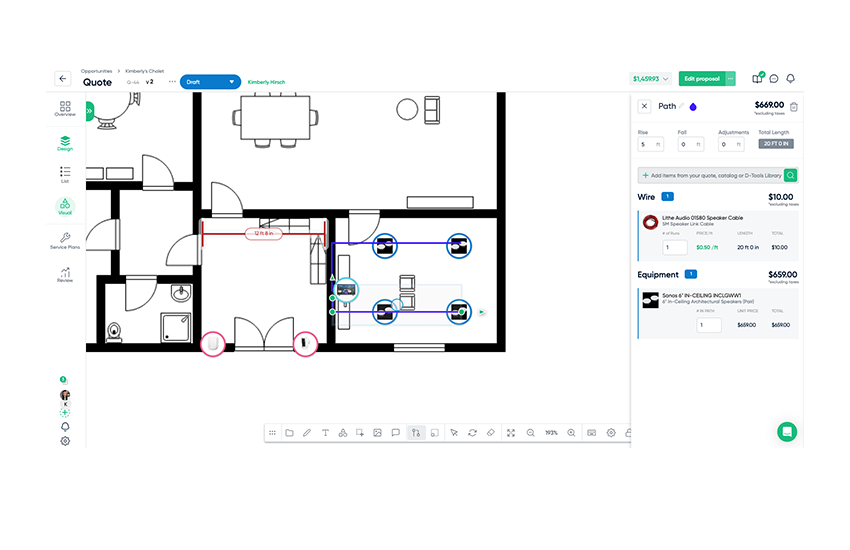
System Design Made Simple with D-Tools Cloud
Streamline your workflow with intuitive tools for visual quoting, drag-and-drop layouts, and real-time collaboration—designed to make system design faster and simpler than ever.


D-Tools Cloud Exclusive
Visual Clarity and Connection Across Every System

System Integrator
Visio Integration
Enhance project visualization and documentation
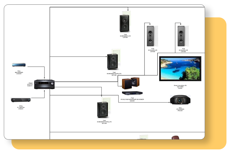
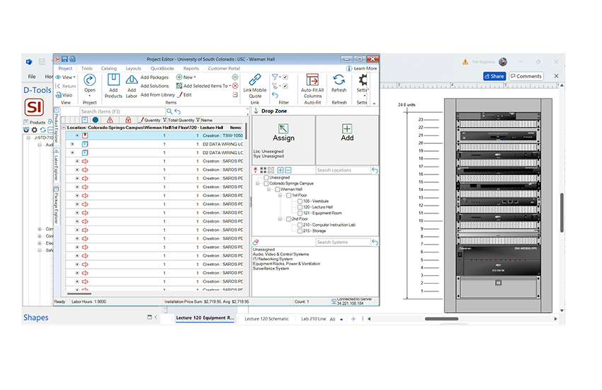
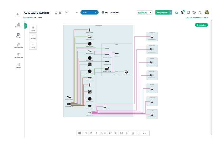
Single-line System Layouts
Easily place equipment from your D-Tools project file onto the drawing surface for clear and straightforward communication with installers.
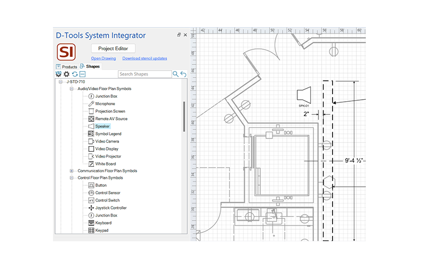
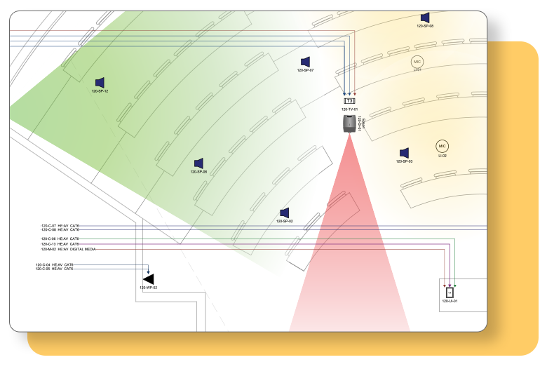
Plan Views
Showcase the strategic placement of equipment within a room or building by importing .dwg files or creating native plan view drawings directly in Visio.
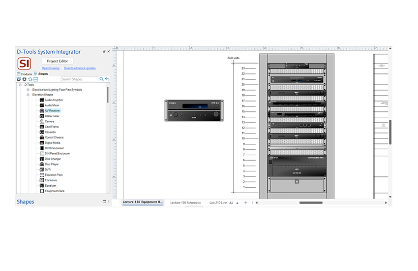
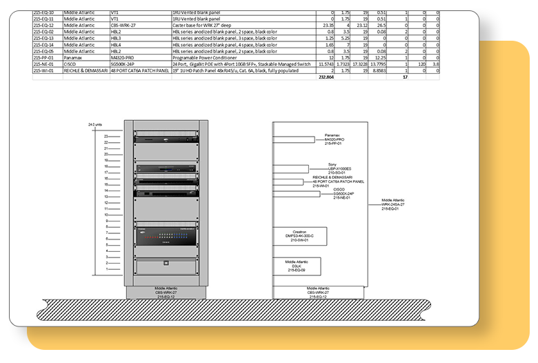
Rack Elevations
Provide clients with a visual perspective of the finished system, especially beneficial for showcasing higher-end systems with custom cabinetry.
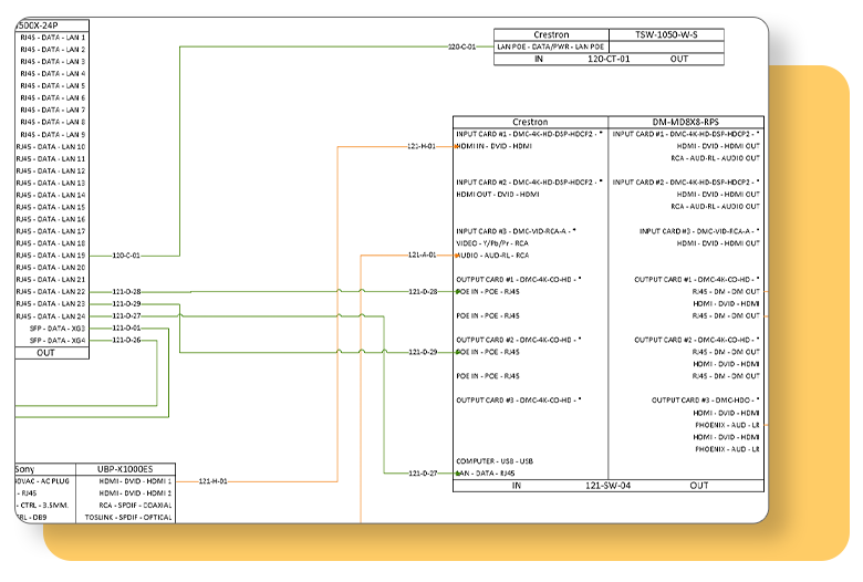
Schematics
Ensure precise connections and generate detailed installation reports for wire schedules, checklists, and labels, assuring a seamless installation process.
Integrated Product Library
Power your system design with industry's largest, most accurate product database
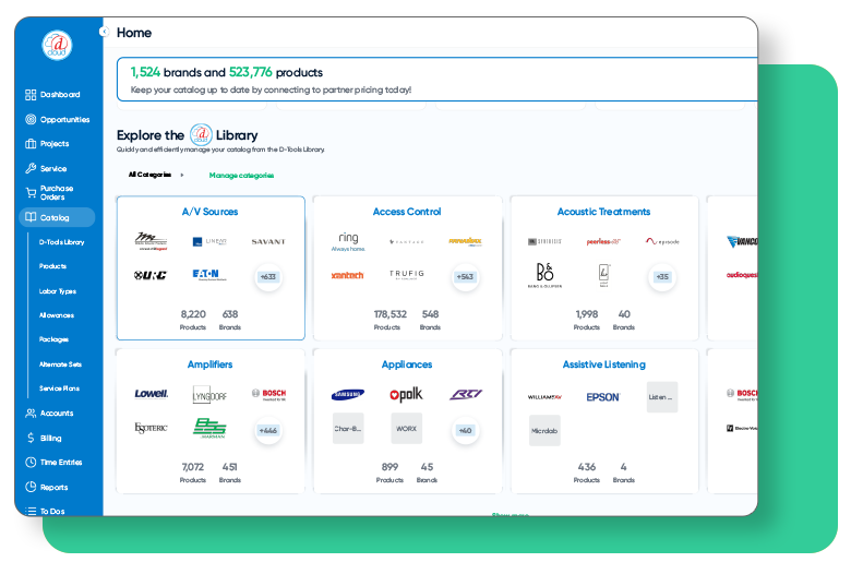
Which product is right for you?
 D-Tools Cloud
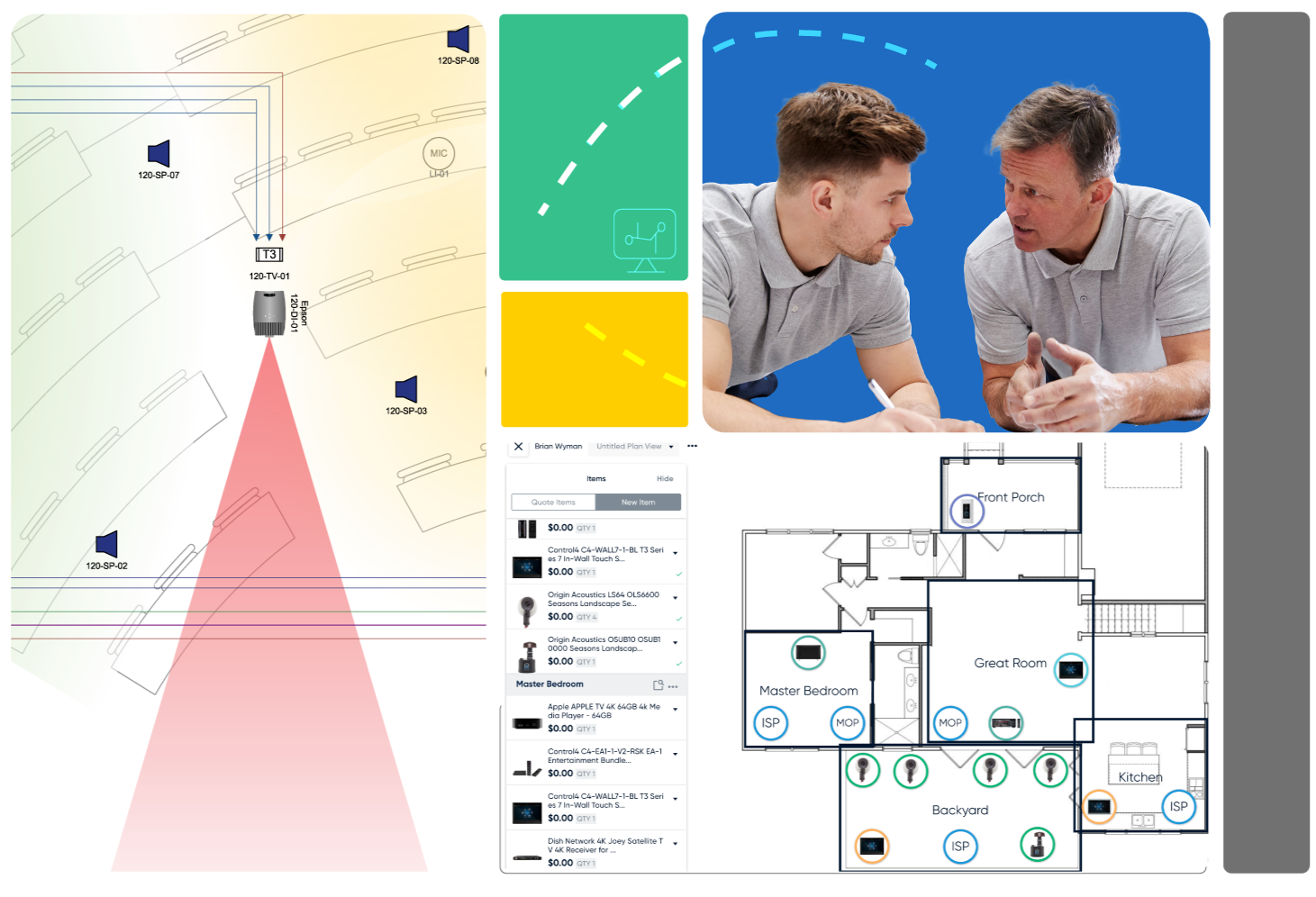
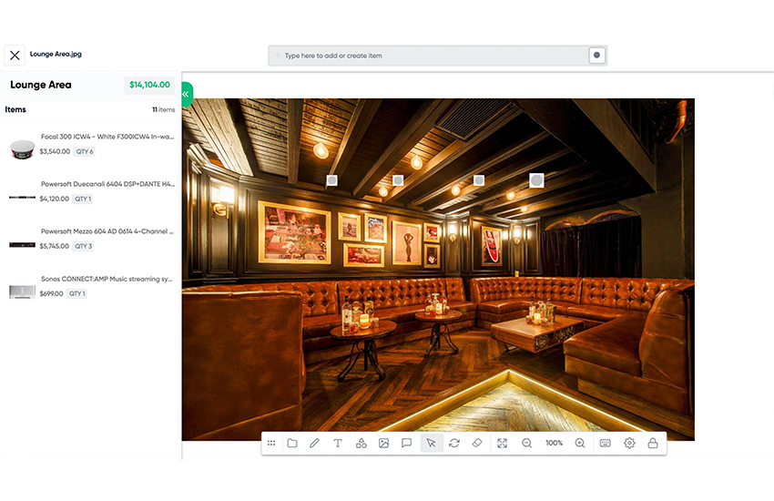
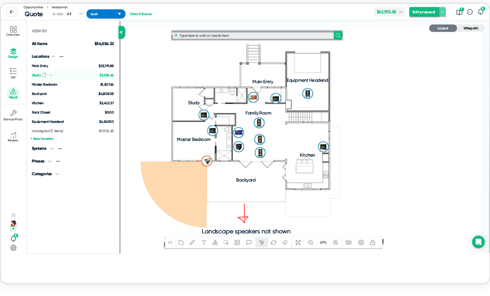
Visual Quoting - Scope & Budget
Use Visual Quoting to generate scope and budgets, validate designs, and collaborate in real-time with customers. Effortlessly upload images and drag-and-drop devices directly onto photos, enabling customers to visualize their systems within their own environment and play an active role in the decision-making process.

.svg) System Integrator
System Integrator