

Microsoft Visio schematic diagrams are easy to draw within D-Tools System Integrator (SI) software for low-voltage integrators through a native integration. Below, we’ll go over the basics of creating diagrams in Visio, the specifics of creating schematic drawings for electrical installations, and some general tips for making a good Visio diagram.
Visio Diagrams: The Basics
Visio is designed to communicate complex ideas as visual diagrams that can be understood at-a-glance. This software is used in a number of fields and industries, whether for creating organizational charts for a corporation or electrical and AV installations for the types of clients we work with at D-Tools. The steps below are the foundation for creating any type of diagram in Visio.

Step 1: Choose and Open a Template
In Visio, templates include shapes, stencils, and grid measurements that help you get a quick start with your diagram without having to create everything from scratch. Here’s how to take advantage of templates in Visio for easier schematic drawings:
- Once you’re in Visio, go to File and then choose New.
- Select the template that best fits your needs, or choose Basic Diagram if you’d like to start from scratch. You can also browse for additional templates by clicking on Categories and entering your desired terms to search for applicable templates. Note that if you're using the desktop link, you may have to specify a specific type of that template; once you’ve done this, click Create.
Step 2: Arrange and Connect Shapes
Once you’ve chosen your template, it’s time to start adding shapes to your Visio schematic drawing.
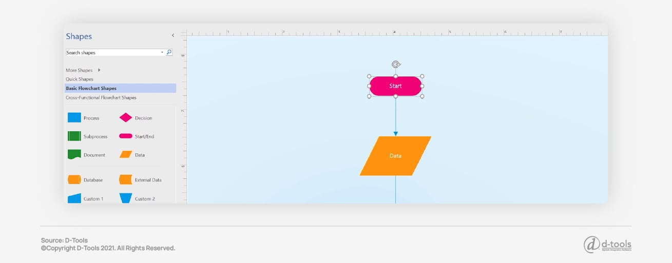
- Go to the Shapes window; choose a shape and drag it onto the canvas to add it to your diagram.
- Hold your mouse over one of the arrows and a mini toolbar will appear with the top four shapes in the Quick Shapes area. Choose the shape you need for your diagram and it will connect to the arrow you’ve selected.
- Another option is to drag all of your shapes onto the canvas. Hold the mouse over a shape until the arrows appear, then grab an arrow and drag it to the shape you want it to connect to.
- In the Visio desktop app, you can drag a new shape from the Shapes window to an existing shape's arrows and they will connect automatically.
Step 3: Add Text to Shapes and Connectors
Adding text helps viewers make sense of your diagram. Here’s what you’ll need to do:
- Select the shape you want to add text to.
- Type in the text; this will prompt Visio to switch the shape into text-editing mode.
- When you’re done, click an empty area of the page or press Esc. This will exit text-editing mode.
Follow these same steps when adding text to a connector. If you want to move the text you’ve entered for a connector, select it again and a small box will appear on the text; this is the handle that allows you to move the text block by clicking and dragging it to your desired location.
Step 4: Customize Your Visio Diagram
Here are some additional ways to customize and edit a Visio schematic diagram.
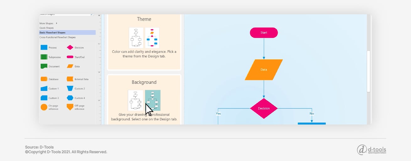
Apply a Theme
- From the Design tab, hover the mouse over each theme. Visio temporarily applies each theme as you hover the mouse over them, giving you a preview of what they’ll look like when selected.
- To see other available themes, click on More.
- Select the theme that you want to apply to your schematic diagram.
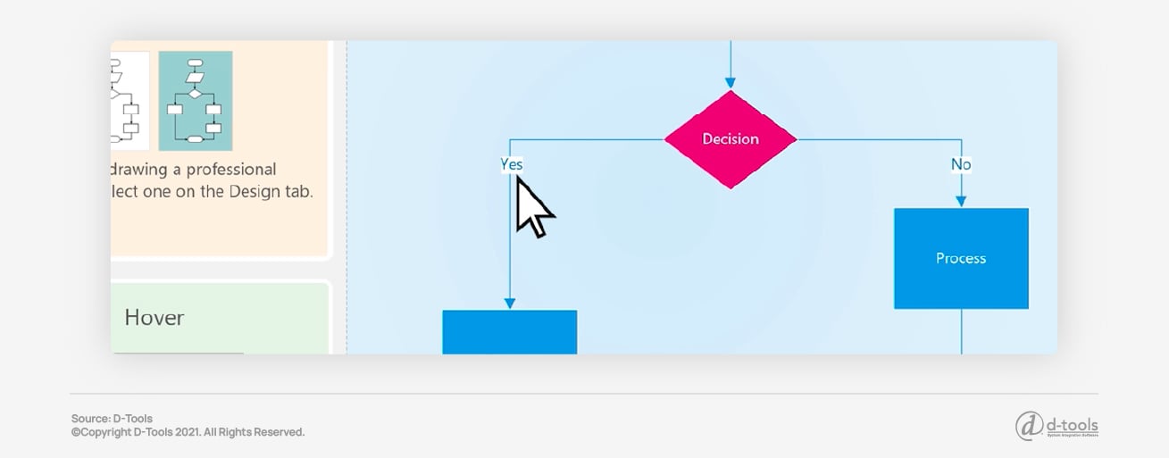
Add a Background to a Visio Diagram
- If you’d like to add a background to your Visio schematic diagram, click Design, and then click Backgrounds.
- Choose the background that best fits your needs. A new background will appear in your diagram, and you’ll also see a new background page called VBackground-1 in the page tabs at the bottom of the canvas.
Apply a Border or Title to a Visio Schematic Diagram
- To apply a border or title, click Design, then go to Borders & Titles. Choose the title style that best fits your needs; the title and border will appear on the background page.
- Find the V-Background-1 tab at the bottom of the diagram and click on it.
- Click the title text; you’ll see that the entire border is selected, but when you begin to type, it will change the title text.
- Type your title and press ESC.
- If you’d like to edit any other text in the border, select the entire border, then click the text you need to edit and begin to type. Sometimes you might need to click more than once to get the text selected.
- Click Page-1 in the lower right corner of the page when you’re ready to return to your schematic drawing.

Creating Electrical Schematic Diagrams in Visio
Along with AV, Visio is well-suited for making electrical schematic diagrams. Once you’ve mastered the steps outlined above, creating an electrical schematic drawing is simple.
- From the File tab, click on New, then search for Engineering templates and choose the one that best suits your needs. Options include:
-
- Basic Electrical
-
- Circuits and Logic
-
- Fluid Power
-
- Industrial Control Systems
-
- Parts and Assembly Drawing
-
- Piping and Instrumentation Design
-
- Plumbing and Piping Plan
-
- Process Flow Diagram
-
- Systems
-
- TQM diagram
-
- Work Flow Diagram
- Choose between the Metric Units or US Units options, then click Create. The template will open an unscaled drawing page that is in portrait orientation. These settings can be changed if needed.
- Drag the appropriate electrical component shapes onto the drawing page. These shapes can have data; enter the shape data to add new data to a shape.
To Enter Shape Data
- Select a shape, right-click, then click on Data, and Define Shape Data.
- In the Define Shape Data dialog box, click each item and select or type a value.
- Use the Connector tool when you want to connect electrical components or connector shapes.
Use the Connector Tool
- Click on the Connector tool.
- Drag from a connection point on the first shape to a connection point on the shape you’re connecting it to. The connector endpoints will turn red once the shapes are connected.
Use Connector Shapes
- Drag a connector shape onto the schematic drawing page.
- Place the connector's starting point on the parent shape that you’re connecting it from.
- Place the connector's endpoint on the child shape that you’re connecting it to. After the connector is successfully glued to the shapes, the endpoints will turn red.
- To label individual electrical component shapes, simply select the shape and type in your text.
The video above demonstrates how to create a Visio schematic drawing in SI v17.
More Tips for a Good Visio Schematic Diagram
Tutorials on Visio schematic drawings take care of the science involved in creating a good diagram, but there’s an art to it as well. This is what sets an adequate diagram apart from one that is aesthetically pleasing and easy to read.
Choose Line Types Wisely
Visio has a number of options for lines—dashed or solid, thick or thin, etc. Since these lines represent connections in your schematic drawing, you’ll need to choose a different type of line to represent each type of connection in your diagram and be consistent in how you use them.
Avoid Visual Clutter
Make sure you have adequate white space in your diagram, as this aids in readability. When your drawing is cluttered, it can be overwhelming to look at and nearly impossible to understand. Take care to balance your objects with your whitespace, and don’t include anything in your diagram that isn’t critical to understanding the system you’re designing.
Pick Complementary Colors
You’re not an artist or an interior designer, but knowing a bit about color is important when creating a schematic drawing in Visio! Use too many bold, dark, or mismatched colors and your diagram will be difficult to read (not to mention a bit of an eyesore!). Instead, try using different shades of one color, or use the color wheel to select a color scheme for your schematic drawing. If you’re using a few different colors, they should all have the same level of saturation—in other words, don’t pair a pale yellow with a primary green.
Use a Sans-Serif Font
Serif fonts have a little more flourish than sans-serif, and in a schematic diagram, you want a font that’s simple and clean; this ensures that your labels can be easily read at-a-glance. Stick with a single font throughout the entire diagram, but use different font weights for emphasis or for different types of labels.
Keep Everything Uniform and Aligned
Labels should always be the same distance from the object or connector they’re labeling, two connected objects of the same type should have the same distance between them, etc. Keeping measurements and alignments uniform helps make your Visio schematic diagram look polished and professional.
Draw with a Single Perspective
If parts of your drawing are in isometric perspective and other parts are top-down, it makes your schematic diagram hard to understand. Choose to use either all isometric icons or all top-down icons for a more balanced view of a system.

Learn More About D-Tools’ Visio Integrations
Utilizing Visio for projects, whether on its own or integrated through business software solutions such as D-Tools System Integrator, eliminates scope creep and re-work by clearly and completely documenting system designs in Visio and/or AutoCAD.
Article originally published January 2020. Updated November 2021.